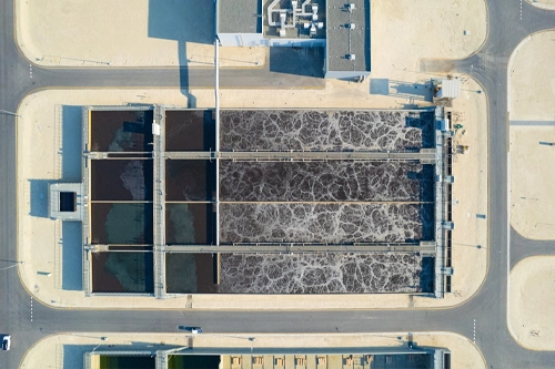
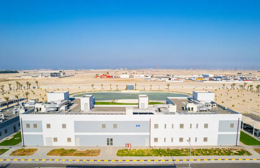
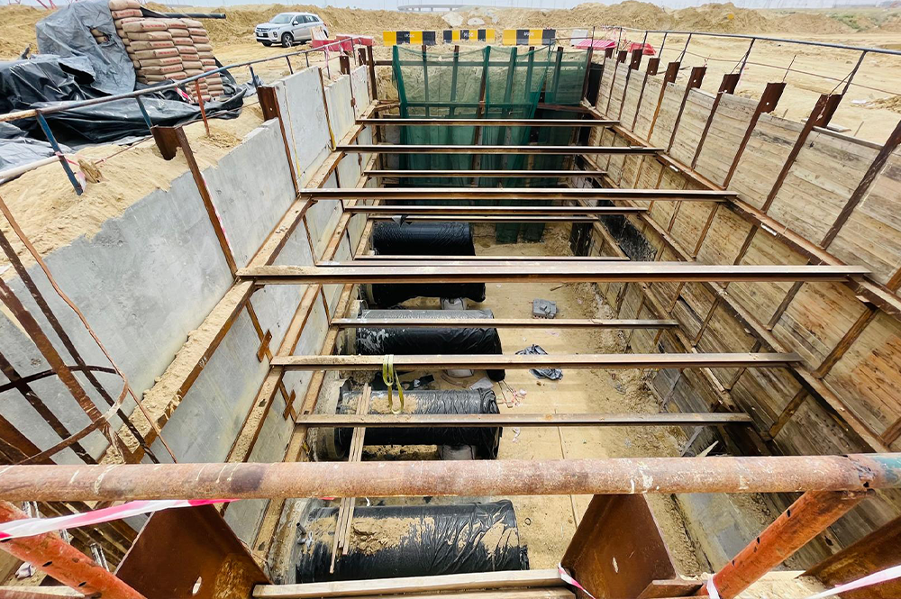
Preliminary Treatment
- Inlet
- Screening
- Grit Chamber
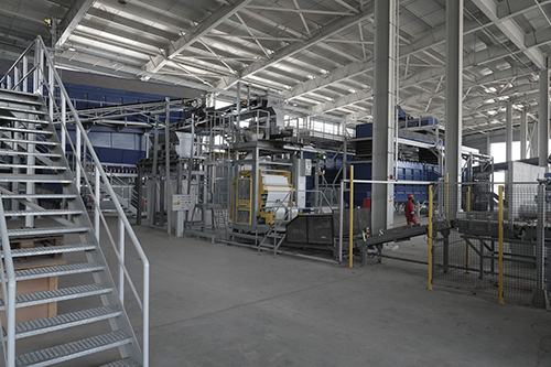
Loading
Nullam dignissim, ante scelerisque the is euismod fermentum odio sem semper the is erat, a feugiat leo urna eget eros. Duis Aenean a imperdiet risus.


| Parameter | Unit | Stage 1 | Stage 2 |
|---|---|---|---|
| Average Daily Flow | m3/Day | 500,000 | 700,000 |
| Maximum Daily Flow | m3/Day | 550,000 | 770,000 |
| Average Hourly flow | m3/Hour | 20,833 | 29,167 |
| Peak Hourly Flow | m3/Hour | 30,417 | 42,583 |
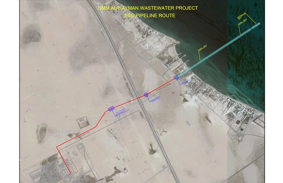
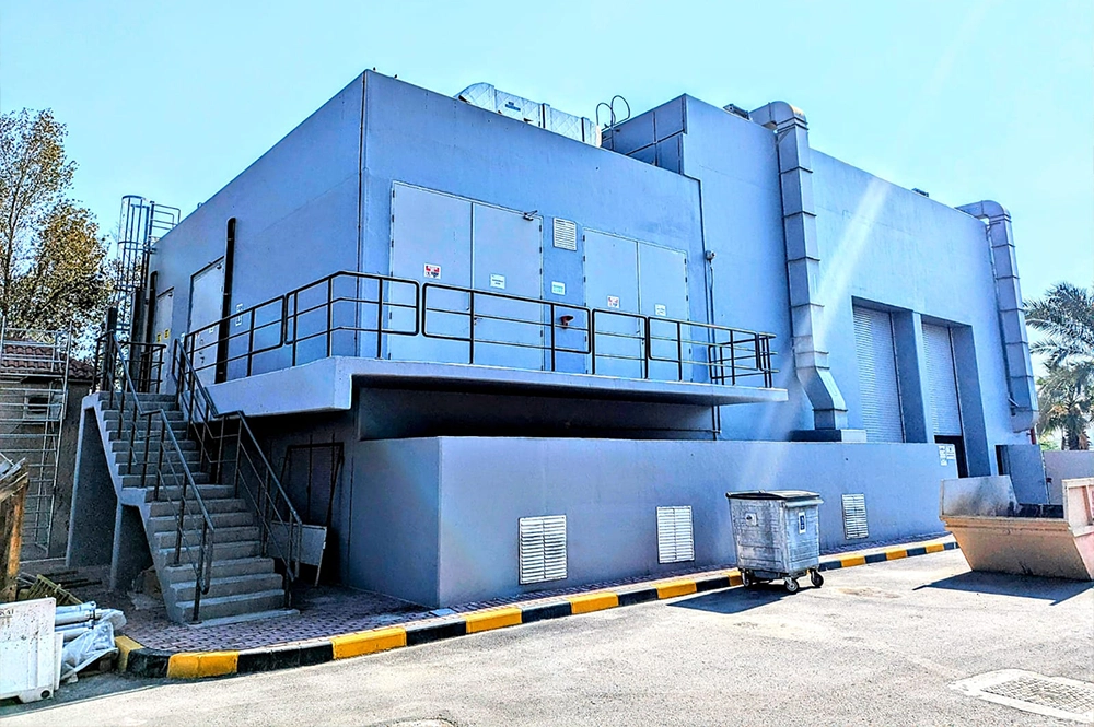
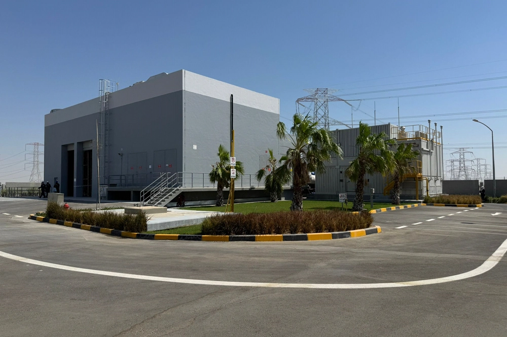
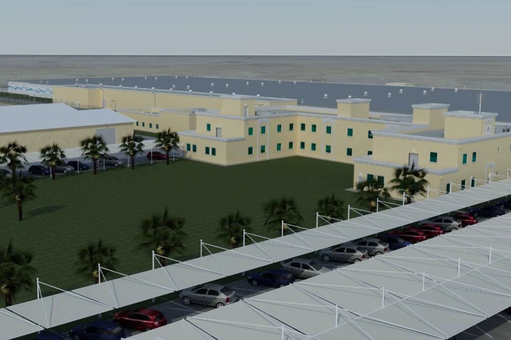
Electrical Special Facility in Umm Al Hayman – “W” 300/132/11 kV Substation and infeed is by 300 kV overhead line between Zour south power station “ZSPS” and Shuaiba ‘W” cut in and diverted to Umm Al Hayman – “W” which is connected by 300 kV UG cable. Umm Al Hayman – “W” substation shall provide power to the Plant and other consumers in the area and it will be operated by MEW after completion.
Electrical Special Facilities in the inside of this Stage 1 Plant area. The total area of ESF is 5,000 m2. Access to the Electrical Special Facilities site is via asphalt road which is part of the road design of the plant. The Electrical Special Facilities road is connected to the main plant access road. The internal access road (inside of the boundary but outside of the fence) will be connected to the public road as part of the project.
The DBO Works of Umm Al Hayman Wastewater Project include development, insurance, design, engineering, procurement, supplying, manufacturing, factory testing, transportation to the site, construction, erection, installation, permitting, completion, testing, commissioning, and carry out other work necessary to construct the Transmission and Distribution System (“TADS”) (including the Egailah Substation and Pumping Station) and the Existing Facilities ROD Works in accordance with the TST PPP Agreement and particularly these Technical Specifications and as applicable for the TADS in accordance with the DBO EPC Contract. The DBO works is divided into 15 Main Assets classified into 4 Wastewater Transmission (“WWTS”) Assets, 6 Treated Sewage Effluent Transmission System (“TSETS”) Assets, and 5 Treated Sewage Effluent Distribution Network (“TSEDN”) Assets.
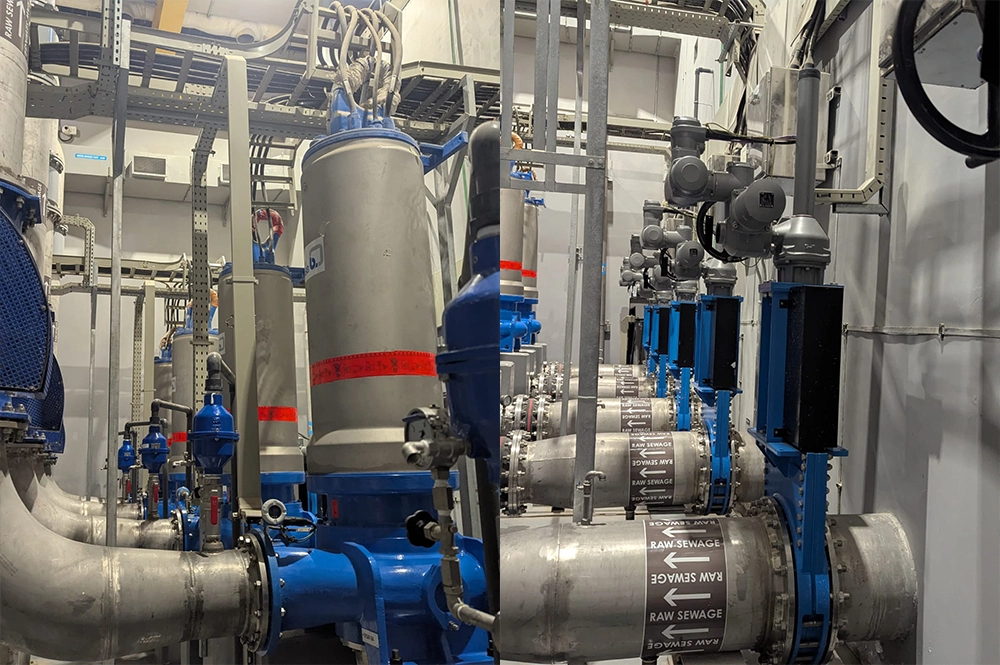
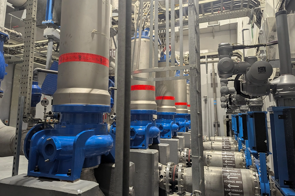
| Main WWPS Egailah | Basement | Roof |
|---|---|---|
| Number of pumps | 10 (8+2) | 10 (8+2) |
| Installation | Dry installed | Dry installed |
| Hydraulic capacity [m3/s] | 0.85 (per pump) | 1.0375 (per pump) |
| Delivery head [m] | 74.6 | 60.6 |
| Rating [kW] | 1,000 | 1,000 |
| Type | submersible | submersible |
| Additional WWPS Egailah | |
|---|---|
| Number of pumps | 6 (4+2) |
| Installation | Dry installed |
| Hydraulic capacity [m3/s] | 0.375 (per pump) |
| Delivery head [m] | 41.60 |
| Rating [kW] | 210 |
| Type | submersible |
Just for the text which is highlighted here, replace it with the one which i am sending you. and also add the image which i will send you here.
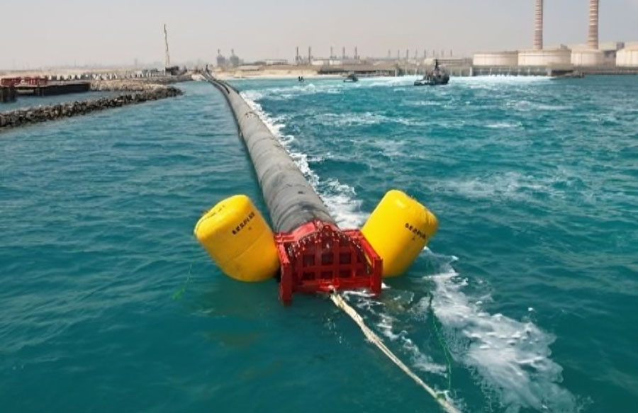
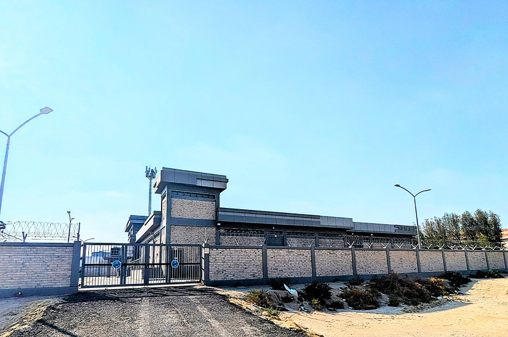
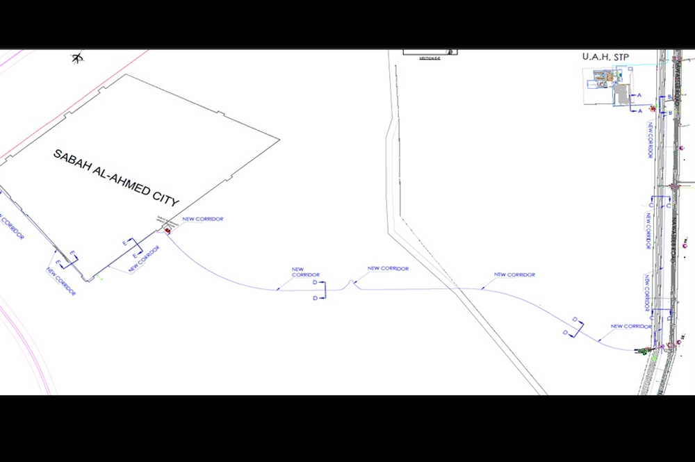
A new Sabah Al Ahmed WWPS ( SAA WWPS ) to be constructed in the south west of the Project area. The hydraulic capacity of SAA WWPS shall be 2.18 m3/s and the wastewater are to be transferred to the UAH WWTP ( Stage 1 ) through a new wastewater transmission system.
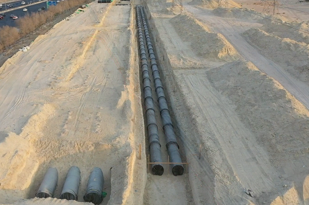
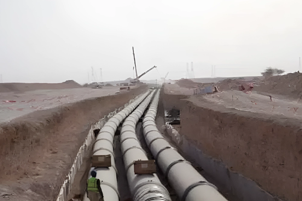
The wastewater transmission mains from SAA WWPS to the UAH WWTP ( Stage 1 ) include ( 2 x DN 1100 ) and the TSE transmission main to the existing Sabah Al Ahmed reservoir ( 1 x DN 1100 ) are to be constructed in a common corridor.
| New WWPS Sabah Al Ahmed | |
|---|---|
| Number of Pumps | 6(4+2) |
| Installation | dry installed |
| Hydraulic Capacity [m3/s] | 0.545 (per pump) |
| Delivery head [m] | 30.7 |
| Rating [kw] | 250 |
| Type | submersible |
| Transmission to | Zone 4 | Zones 5,6,7 (Riqqa) | Zones 1,2,3 | Zone Sabah Al Ahmed |
|---|---|---|---|---|
| Number of pumps | 3 (2+1) | 5 (4+1) | 4 (3+1) | 3 (2+1) |
| Hydraulic capacity [m3/h] | 850 | 4,464 | 1,584 | 2,052 |
| Delivery head [m] | 56.6 | 160.5 | 80.0 | 117.8 |
| Rating [kW] | 200 | 2,454 | 560 | 831 |
| Type | Horizontal split case | |||
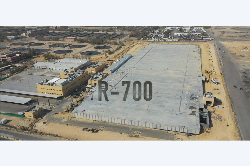
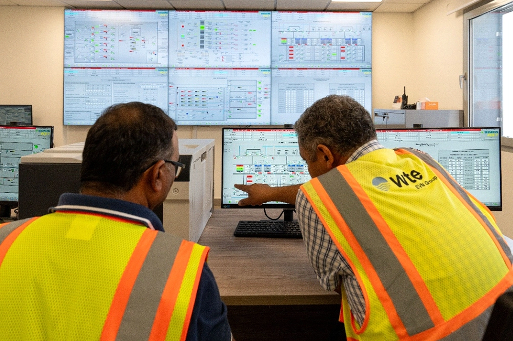
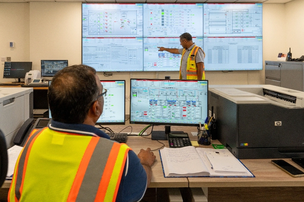
The TSE Transmission System and Distribution Network are monitored and controlled from the Data Management Center (DMC). DMC is located at existing Riqqa WWTP with new TSE reservoir R700. The DMC has Office space for approximately 200 MPW employees and two fully furnished laboratories that are equipped for the use of the Project Company and the Buyer to carry out the TSE analysis signals. The signals will be transferred via new optical cable. Connected stations are: WWPS Egailah, WWPS Sabah Al Ahmed, WWTP Umm Al Hayman, TSE Reservoirs, TSE Secondary Reservoirs and Pipe chambers.
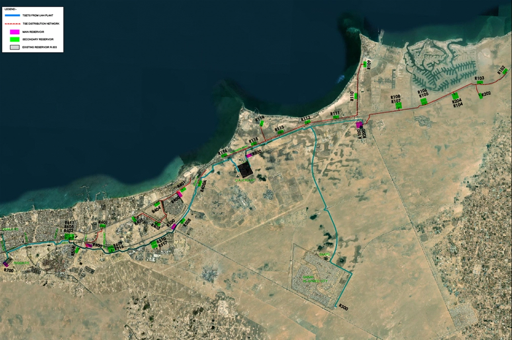
The transmission mains are connected to a network of 7 strategic and 32 secondary reservoirs the largest reservoir is R700 with volume equal 160,000 m3. The remaining is 6 identical strategic reservoirs located in zone 1, 2, 4, 5, 6 and 8 with volume equal 40,000 m3 each. The strategic reservoirs feed a total of and 32 Secondary Reservoirs 27 with a volume 2,000 m3 and 5 with volume 3,000 m3.